| 1) How Do I wire Limit/Home switches to the 3/4 Axis Drive board |
The drive board has nothing to do with switch inputs other than
provide a place to make a connection to the unused parallel port I/O. These connections are made at the black 10-position
screw terminal. How the extra I/O are used are determined by the software, and the type of switch being used. An
example of a switch input can be seen here:
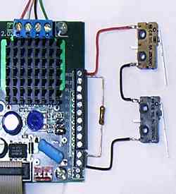
The Black wire goes to GND and connects to one side of the NC (normally closed) switch. The 10K resistor goes from
the +5V to one of the parallel port inputs. Also connected to that input is the other side of the NC switch (or
series connect switch as seen in the photo).
More info regarding connections to CNC4PC can be found here: http://www.plasma777.com/driver/xylotex.htm |
| 2) The drive can handle 2.5A/phase motors. There are 2 phase per motor, and 3
(or 4) motors per board. How can a single 5.0A/24VDC Power Supply handle all of this? |
The switching action of the Xylotex controller plus
the inductance of the stepper motor have a sort of "transformer" effect. Suppose the power supply is
24 V, but the motors are need 2.4 V at 2 amps for full torque. If the Xylotex is set to deliver 2A to the motor,
it does deliver 2A average. But the power supply only has to deliver 0.2 A at 24V, or a little more. 0.2 A at 24
V (from the power supply) is the
same amount of electrical energy
as 2.0 A at 2.4 V (delivered to the motor), so there are no energy conservation laws being broken. But the power
supply current is far less than the motor current.
What actually happens is that the Xylotex draws current from the power supply about 10% of the time, and uses nothing
the other 90% of the time. The peak current from the power supply is in fact about 2.0 A, but because of the duty
cycle the average current is only 0.2 A. Average current determines the size of power supply needed. But the motor
current averages 2.0 A all the time, so the motor develops full torque.
The place where you need more current from the power supply is at higher motor speeds. As the motor runs faster,
the winding current stays constant (thanks to the Xylotex) but the voltage goes up, which requires more power.
Since the power supply voltage remains constant, the power supply *current* increases in step with the motor *voltage*.
So to run motors fast, particularly with more than one motor moving at once, you need more current. |
| 3) What Software can I use with the Xylotex Drive? |
|
The drives requires standard STEP and DIR signals.
These signals are usually generated via CAM software programs running on a suitable PC with a parallel port. These
CAM programs accept g-code files generated by CAD programs such as BobCad or Autocad. The Xylotex pinout requirements
for the parallel port are:
STEP X - Pin 2
DIR X - Pin 3
STEP Y - Pin 4
DIR Y - Pin 5
STEP Z - Pin 6
DIR Z - Pin 7
STEP A - Pin 8
DIR A - Pin 9
The DIR line need to be stable 200nS before and
after the rising edge of the STEP line.
The following is a partial list of CAM software
that will work with the Xylotex drive:
- Mach3 - http://www.machsupport.com
- TurboCNC - http://www.dakeng.com
- EMC2 - http://www.linuxcnc.org/
- KCam - http://www.kellyware.com
- CNCPro - http://tech.groups.yahoo.com/group/CNCPro/
|
| 4) My PC doesn't have a Parallel Port. Can I use a USB-Printer adpater? |
| No. The STEP and DIR signals need to have an even
pulse train output. Normal USB-printer adpaters are not "real time" and would provide a ragged pulse
train. This would cause the motors to stall. There are some Windows based programs that can commincate with specific
USB-Pulse generator adapters. See the Links page: http://www.xylotex.com/links.htm and look under the heading: Interesting USB CNC devices. |
| 5) Are the drives opto isolated? |
| No. The 3 and 4 axis drive boards have no optoisolation
on them. They do have R/C filtering and HCT541 logic buffering on them. The R/C filtering helps keep out spurious
signal noise, while the logic buffer allows the drives to receive signals from "green" PC's that may
have low voltage signals from the parallel port. Opto isolation becomes necessary in especially noisy environments
or with voltages higher than the 3 and 4 axis drive boards use. |
| 6) How do I add relays for coolant pumps or spindle |
| You would need to take one of the parallel port outputs,
and apply it to some sort or relay driver. SSR relays have built-in control, while mechanical relays will require
an external relay driver. If you need relay control, an external break-out board with these capabilities is recommended.
For some break-out boards look under the heading of : CNC Hardware & Accessories Links, on the web page:http://www.xylotex.com/links.htm |
| 7) Do I have to run all of the motors and/or drives? |
| No. Unused axes should be disabled, but the drive will not be harmed if you do not have motors plugged in. Never
plug or unplug a motor with the drive powered up. |
| 8) Can I use different motor sizes for each axis? |
| Yes, Each drive on a 3 or 4 axis drive board acts
independently of the others. For example you can have the X and Y run 269 oz.in. motors while the Z axis runs a
425 oz.in. motor. You need to set the Vref for each drive according to its motor requirements. |
| 9) Can I run two motors from one axis? |
| No. If you need to run 2 motors for an axis (i.e.
two motors driving the gantry on a router), then you should "slave" two motors. For example with a 4
axis drive board, the "A" axis would be slaved to the "Y" axis signals. Software such as Mach3
will allow axis slaving. |
| 10) Which motors will be best for my Sherline/Taig/X1/X2? |
| For higher pitch leadscrews like those found on the
Sherline, Taig, and smaller SIEG machines, the 269 oz.in. motor is the better choice. It will give better high
speed performance when compared to the 425 oz.in. motor. |
| 11) Which motors would be best for my router? |
| If you are using high pitch leadscrews (15 to 20 tpi)
then the 269's would be the recommended choice. If you are using lower pitch screws, like 5 tpi ballscrews, then
the 425's would be the better choice. If you have ~10 tpi screws, the 269's will give better rapids, but lower
low-speed torque. The 425's will give more low-speed torque, but slower rapids. The actual power from the drive
board does not change (2.5A at 24VDC). The 425's are like a car running in low gear, the 269's are like running
in higher gear (the power source -the car's engine - doesn't change significantly). |
| 12) How do I set up the microstep settings |
| The step settings headers are in the center of
the board along with the ENA header. The drive ships with the ENA header jumpered. The other two pin sets used
for step setting are not jumper, thus placing the drive in 1/8 step mode. To see how to set the step rate, look
at this document: http://www.xylotex.com/StepSetting.pdf |
| 13) What are the pinouts for the unused parallel port I/O on the black screw terminal? |
See the last page of the datasheet for the pinouts.
For example, you will see the notation "P10". This means that the coresponding terminal connects to DB25
Parallel port pin number 10
4 Axis Data Sheet: http://www.xylotex.com/XS3525V400.pdf
3 Axis Data Sheet: http://www.xylotex.com/XS3525V202.pdf |
| 14) Can I run 6-wire motor with the Xylotex drive? |
| Yes, see the last page of the datasheet (see #13 above)
for the "half-winding" and "series winding diagrams." 6-wire motors rated above 3.5A should
be run in "series" mode, while motors 3A or less should be run in "half winding". In series
mode you use from HALF the rated amperage (you are using twice the number of wire turns) of the unipolar mode (on
up to rated current X .71). For half winding, you use the rated motor current. |
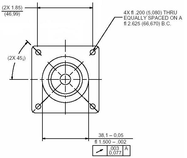
| 15) What are the Stepper Motor Mounting dimensions? |
| Both the 269 oz.in. and trhe 425 oz.in. stepper motors
have a Nema23 mounting faceplate. A drawing of the faceplate with dimensions can be found here: http://www.xylotex.com/images/Nema23.jpg |
| 16) What are the manufacturere numbers of the motor & cable connectors used? |
Description Molex Part#
Motor Crimp Connector 02-06-2103
Motor Plastic Shell 03-06-2044
Cable Crimp Connector 02-06-1103
Cable Plastic Shell 03-06-1044
Available from:
http://www.mouser.com
Cabling can be purchased from places
like Home Depot. Get 4 conductor, 18 guage, Stranded cabling.
The Crimp pins used are:AMP Part #:19212-0003-C available from http://www.digikey.com |
| 17) What RPM can I get with your motors |
| There is no real RPM rating for the motors. Unloaded they will spin very fast. All stepper motors loose torque
as they go faster, and will have more torque at lower speeds. Your actual traverse rate in IPM (inches per minute)
will depend on the mass and friction of the machine. Cutting rate will also depend on cutter sharpness, width and
depth of cut, spindle speed, hardness of material, etc. When using 10 TPI screws with the 269's you can get between
50 and 75 IPM. When using the 425's you will get around a max. of 50 IPM, but with more lower speed torque. If
you have 5 tpi screws, then you are better off with the 425's. With the 425's and 5 tpi screws on a smooth running
machine you can get over 100 IPM. Your actual rapid speed will depend on the screws being used and the motor selected
(as well as the dynamic of the actual machine). |
| 18) The motors are rated at 2.8A, but the drive can only output a maximum of 2.5A |
You will not get full rating from the stepper motors since you can't go past 2.5A/phase with the drive. But, in
most cases, you actually want something even lower than 2.5A The reason is that at higher step rates
the current may not have time to build up to full level in the motor coils before the next step pulse comes in.
This will mean a distorted power sine wave and rough motion. Using a lower Vref means the current can build up
to the proper levels and produce a smooth sine wave to the motor coils. This helps minimize the distortion problem,
which allows for smoother motor movements (the reason you want microstepping in the first place). The smoother
motion allows more of the high speed torque to be delivered to your load rather than
in to overcoming vibrations and oscillations. You will see lower slow speed torque at a lower Vref setting, but
for most people the low speed torque produced is more than adequate to do the job. |
| 19) What is all this about RoHS and not shipping to the EU ? |
| On July 1st, 2006, The EU started enforcing the RoHS law. RoHS stands for Reduction of Hazaradous Substances. It
restricts importation in to the EU of certain things, one of which is lead (Pb). Xylotex products are made with
lead based solder, so are restricted from being imported in the the EU, thus Xylotex does not export to EU countries. |
| 20) What are the Molex .1" housing numbers? |
Part type and Molex part #
2 Pin Housing 22-01-2027
4 Pin Housing 22-01-2047
5 Pin Housing 22-01-2057
9 Pin Housing 22-01-2097
10 Pin Housing 22-01-2107
The crimp terminals are 08-50-0114
These parts are available from http://www.digikey.com |
| 21) What's the deal with Static Discharge and Grounding |
You can't ground the drive board to protect it from static discharge, you need to keep it away from static charges.
For the most part, this means keeping it in an eclosure where static charges (fingers, hoses etc.) can't get to
it.
The more important thing is to keep static charges from getting to the drive board via the cabling/wiring.
Vacuum (dust collection) hoses are a major source of static charges with wood working routers. There must be an
exposed copper wire/cable (usually flexible braded copper - perhaps tin plated) running through the entire inside
length of the vacuum tube where it will come out at the motor end and make contact earth ground. This earth
ground would be the same as the round prong on the power cord, or the green wire inside the power cord. Ungrounded
vacuum hoses can build up a large static charge (in the thosuands of volts). This can easily pass through regular
insulation (usualy rated between 200 and 600 volts), and travel down through motor/signal cabling to the drive
board which has an absolute maximum rating of 35VDC. |
| 22) Is it OK to crank the motors manually |
| Yes, turn off the power to the drive and crank them at manual speeds. |
| 23) The red LED on the drive board glows dimly even after turning
of the power to the drive. |
| The signals from the parallel port are back driving power in to the board. This is OK, and is not a problem |